Rebar lap length is one of the critical parameters to be aware of when reinforcement designing, detailing, and construction. It’s important to provide enough lapping length and position it correctly in order to minimize any negative effects.

Simply, the lep length is to transfer the tensile or compression forces in the concrete. but differences in lapping techniques, preferred locations, plus the appropriateness makes lapping is not so straight forward.
Rebars come in 6m and 12m in length typically. When reinforcing concrete members more than 12m in length, lapping is mandatory. There are several ways you can lap or splice the reinforcements.
- Contact & non contact lapping
- Welding
- Mechanically splicing
Contact and non-contat lapping
This is the most common and easiest method for rebar lapping. You only need to provide enough overlapping lengths for bars. Lapping length varies with the structural member. For one bar size, lapping length varies between beam and slabs. Likewise, construction codes suggest different lapping lengths for reinforcement in the different structural components.
In this method, forces transfer from one bar to the other through concrete. Noncontact lapping length generally shorter than contact lapping length. It’s because of non-contact lapping has a full surface area to transfer force to the concrete. in contact lapping case, one side of the rebar is covered by the other rebar. However, with contact lapping, the spacing between adjacent rebars are higher. This is helpful when compacting the concrete. otherwise, there won’t be enough space to insert the poker vibrator.
Lap length varies according to the bar size as well as concrete strength grade. Larger bars require long lap length because the transferring load is high. Concrete with higher strength requires less lap length because it can bear higher stress.
Lap lengths for non contact lapping (in inches)
| Rebar | Diameter (in) | f ‘c = 2500 | f ‘c = 3000 | f ‘c = 4000 | f ‘c = 5000 |
| # 3 | 0.375 | 28 | 24 | 22 | |
| # 4 | 0.5 | 41 | 37 | 32 | 29 |
| # 5 | 0.625 | 51 | 47 | 40 | 36 |
| # 6 | 0.75 | 61 | 56 | 48 | 43 |
| # 7 | 0.875 | 89 | 81 | 70 | 63 |
| # 8 | 1.0 | 102 | 93 | 80 | 72 |
Lap length for contact lapping (in inches)
Thumb rule : Contact lapping length = non contact lapping length x 1.5
| Rebar | Diameter (in) | f ‘c = 2500 | f ‘c = 3000 | f ‘c = 4000 | f ‘c = 5000 |
| # 3 | 0.375 | 42 | 36 | 33 | |
| # 4 | 0.5 | 62 | 56 | 48 | 43 |
| # 5 | 0.625 | 77 | 70 | 60 | 54 |
| # 6 | 0.75 | 92 | 84 | 72 | 65 |
| # 7 | 0.875 | 134 | 122 | 106 | 94 |
| # 8 | 1.0 | 153 | 139 | 121 | 108 |
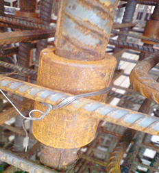
Welding and mechanical splicing
Welding and mechanical splicing both are rebar connecting methods. These splicing methods are unique. Some rebars don’t support welding because it heats the bar and then allowed to cool under normal conditions. This will reduce its toughened strength under special curing conditions.
10 times the diameter is the welding length for welded lapping. If welding is done at both sides, 5d is enough.
Aside from those common methods, there are few occasionally used techniques for lapping.
- Flash butt welding
- Eectroslag pressure welding
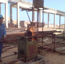
Flash butt welding
In butt welding, rebars are connected using a high amperage current. The machine connects the ends of two rebars melted due to the current. The process needs special instruments as well as special locations. But welding creates sparks around the working area, specialized safety equipment is essential for this method.

Electroslag pressure welding
I have seen this method using once for high-rise vertical towers. It was effectively useful for lapping 32 mm bars in thin concrete walls where normal lapping is not practical. The technique is similar to flash butt welding. Melting is initiated by an electric arc. However, the connection is forged using metal slag powder. When the bars touch each other, current path forms. It makes the slag melts and forms the connection.

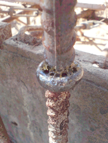
Typically the slag reaches about 3500°F when forging the connection. So this needs a specialized person and many safety precautions to satisfy.
Lapping position
The position of lapping is important as much as lapping length for reinforcement. We always try to avoid the high stressing areas when locating the splice. For common members like slabs, beams, and columns most ideal places for laps are shown below.
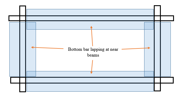
Slabs
Generally, hogging moments induce near the beams when a constant area load acting on the slab panel. This allows us to place the bottom bar (sagging bar) in those areas. However, if the slab is doubly reinforced, try to splice the top bar in the middle.
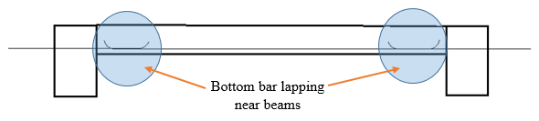
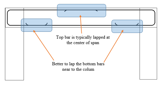
Beams
The typical bending moment diagram of a continuous beam will be like follows. So it’s obvious to lap the bottom bars near the column while lapping the top hogging bars in the middle.

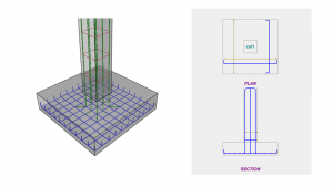
Columns
Columns usually have a less bending moment at the center. Verticle loads as well as lateral loads induce bending moment at the top and the bottom of the column. It’s better to place the splice in the middle of the column. However, this arrangement is difficult to apply. Handling 6m rebar and lapping at the center is quite hard. Due to the weight, the bar goes here and there and reinforcement works will be difficult.


In most cases, column rebars are lapped in the bottom of the column with higher lap length. Consider 1.5 times the nominal lap length. However, this should comply with relevant earthquake detailing guidelines.